So this shedweek I've been back on the tools again. With my repaired mill working properly again I've been able to make a start on the left hand crank arm. This arm also doubles as the planet gear carrier that holds the planet in constant mesh with the sun. It is a complex part in that it has three bearing surfaces, two of which are concentric and the third has to be very accurately positioned relative to the first two. This bearing spacing is what determines the gear centres and must be carefully measured.

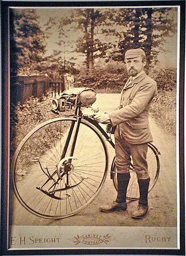
The left crank arm / plant gear carrier from the original geared facile.

Roughly half of the originals I have seen have this face slightly hollowed out.
This one doesn't, it has the patent information stamped on it instead.
We know from previously that my gears run on theoretical centres of 2.977". I wanted to check this empirically before spending hours making a component that doesn't fit. I contrived a set up in the lathe where I drove the sun gear in the chuck and was able to feed the planet gear in and out of mesh on the cross slide. It turns out that my gears are happiest at centres of 2.970", only a 7 thou difference but I'm a pedant (no, really?) The nitriding process will very slightly increase the size of the gears, but this will not be measurable with my equipment. Also recall that involute gears can cope well with incorrectly spaced centres but I'd much rather make the centres too wide than too tight. The original facile I rode had very sloppy gears and it was unnoticeable when riding.

The sun is driving the planet. Of course in use, the planet will drive the sun.
As before the crank arm will be made from 4140 and nitrided, the most economical way to get 4140 of the right thickness is to start with round bar. A little trig to calculate the minimum size that contains the shape and then get busy on the mill.

Mill a flat on one side of the appropriate depth. In this case 0.375" which happens to be...

...the thickness of an old bearing. Bearings make excellent parallel spacers so I can flip
it over and machine the opposite side and ensure both faces are parallel.
Now we have to apply a little thought about how to get those two holes accurately centred. Clearly, two centre punch marks aren't going to be accurate enough, the quickest and easiest way is to use the dials on the mill and the mill as a drill. First part is to saw off the work and remount directly on the mill bed such that it is parallel to the ways, in this case the y-axis. A dial gauge is invaluable here. Then using an edge finder, we can determine the centre of the work and lock the y-axis. Any hole then drilled along the x-axis will be on the centre line. Next use the edge finder to calculate the x position of the first hole on one of the bosses. Lock the x-axis and centre drill that hole. Then simply move the bed 2.977" using the x-axis dial, lock and centre drill the second hole.

Holes at 2.977" centres (reasonably accurately)
Then we have to remount on the faceplate for the next operation. Use a live centre to hold the work centred on the planet boss and clamp (very) firmly. Anything mounted this eccentrically is going to cause serious vibrations when run at any speed so it is crucial to balance the faceplate. In Sparey's book, he features lots of pictures of change gears used as counterbalances. I don't like doing this, change gears are expensive and should be treated with a little more respect whereas lumps of scrap metal with holes are plentiful and cheap. I have a cunning little tool that helps enormously with balancing faceplate setups, I simply turn the tail stock around and mount it in the Morse taper and hang the faceplate off the end of the lathe, it spins freely and will always hang heaviest part down. By playing around with counterweights and sliding them in or out, it is possible to balance even the most awful set-ups.

A balanced set-up.
Using a live centre as a steady, and periodically checking for deflection with a dial gauge directly onto the live centre, it is now possible to machine the boss. Small feeds are needed as this is an interrupted cut and any hard blows will knock the work off centre. Not what we want.

The planet gear boss at final size.

On all of the faceplate set-ups, I periodically check for movement of the centre with a dial gauge.

Now I can make a faceplate clamp just to suit this boss, to hold the work very tightly
so I can bore the hole and the inner bearing surface for the planet gear.

Then flip it over, re centre and machine the outer bearing surface.

Stuff the outer bearing full of balls and check for fit with the adjuster in place.

Next remount (again) and machine the live axle boss and bearing surface into the other end.
Also tap the boss for the live axle (5/8" cycle thread). I didn't need to make a special clamp for this end as the other end has a through hole by now which made the set-up more secure than before. These faceplate set-ups were very quick to machine but took much longer to align. The difficulty is that as you start to bolt things down to the faceplate, you get movement, not much but enough to throw the work off centre or out of alignment. My dial gauge is very sensitive at 10,000 of an inch increments and it make the adjustments easier. you have to go through a cycle of tighten, check, adjust, re tighten etc. until everything was exactly in the right place and tightly bolted up

All the machining is now complete. I just needed to
clean up the faces with a file ready to mark out the profile.


A few minutes with a hacksaw and then a little longer with a file.
I still need to drill and tap for the oiler and the patent information needs to be stamped into the outer face, but I need excellent light for this so I'll do it outside at the weekend. Also the tapered holes to lock the arm to the axle still need to be figured out. More later.
Next week, I'll make the live axle which is trivial and then tackle the planet gear, how exciting is that?
In other news, the bridge over the Ashley river reopened for a nanosecond allowing me to get a ride in on my favoured route. We had a full day of heavy rain yesterday so it is now shut again. Sigh. A work colleague suggested that the current state of affairs is no different to having a ford instead of the broken bridge. When the river is low, you can drive over and when it is high you can't. It would be a lot cheaper.
Also, the Old Waimakariri Bridge is now also shut for unknown reasons since the river is very low. I'm not sure if cyclists are allowed over it. If not I'll be forced to ride down the motorway which is Not Fun. Honestly, the infrastructure around here is pants, none of it is even earthquake damage.


